REPAIR SHOP
Repair of Peavy Tour 700 Amplifier
Fault - Dead and blows fuse in rear panel
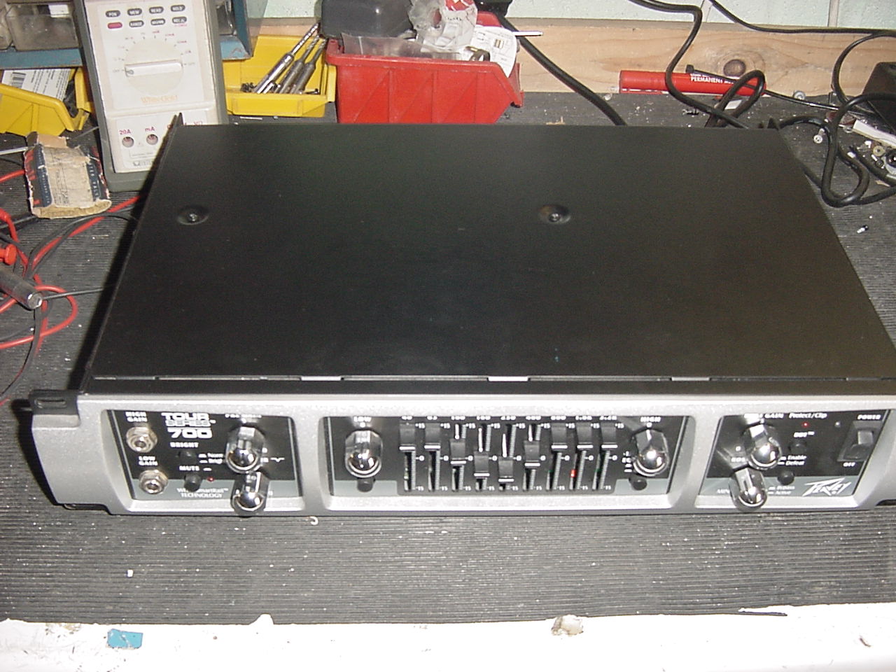
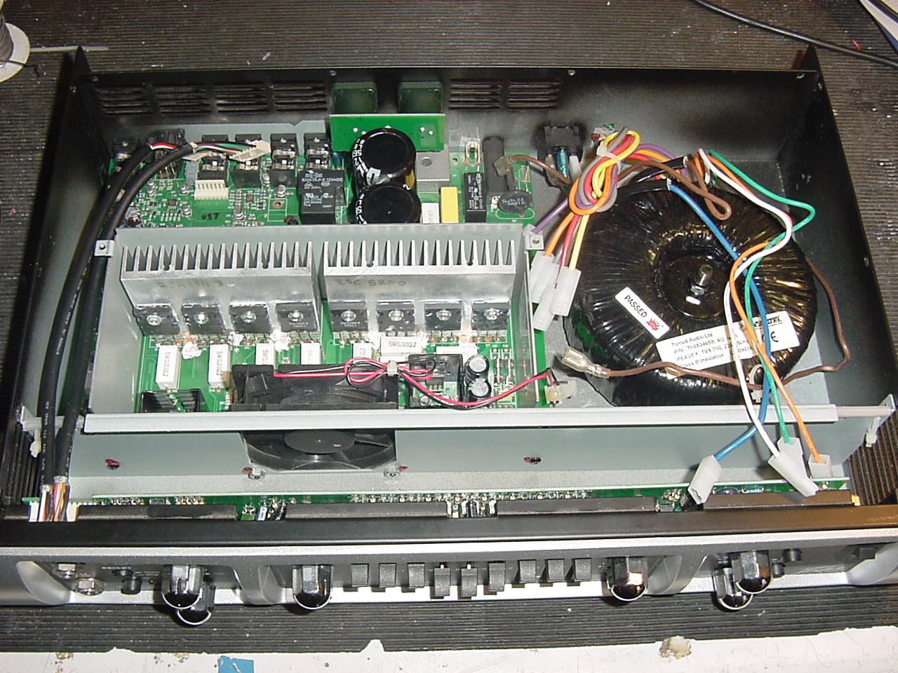
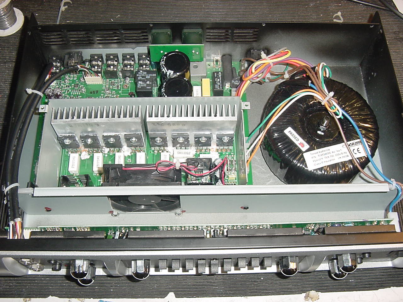
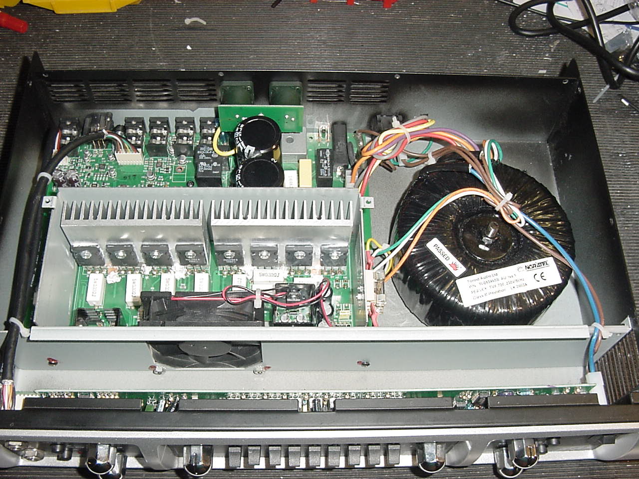
Opened the Amplifier up revealing neat main board/heatsink assembly and torodial transformer
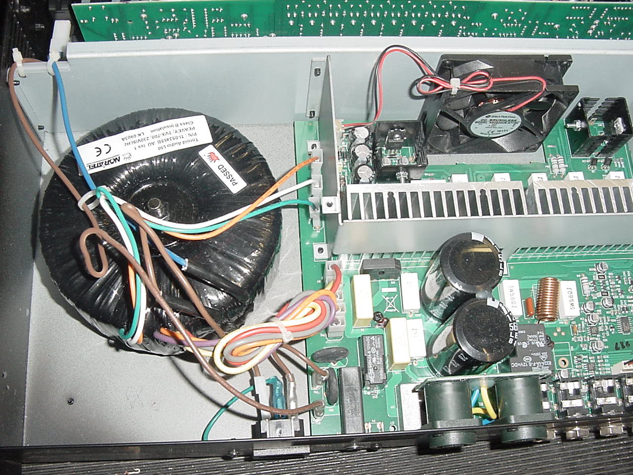
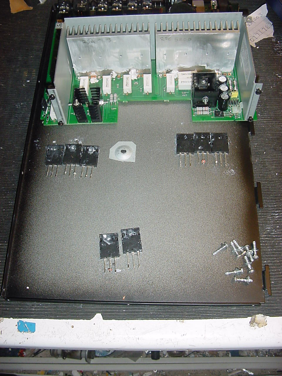
Removed the main board and chassis for testing
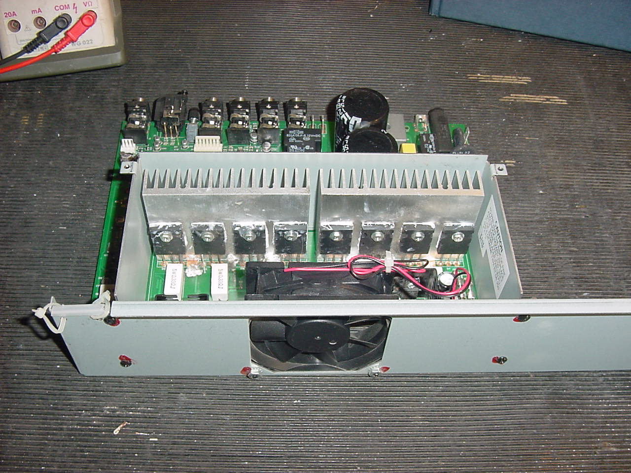
Removed fan assembly chassis giving good access to the power transistors and main board
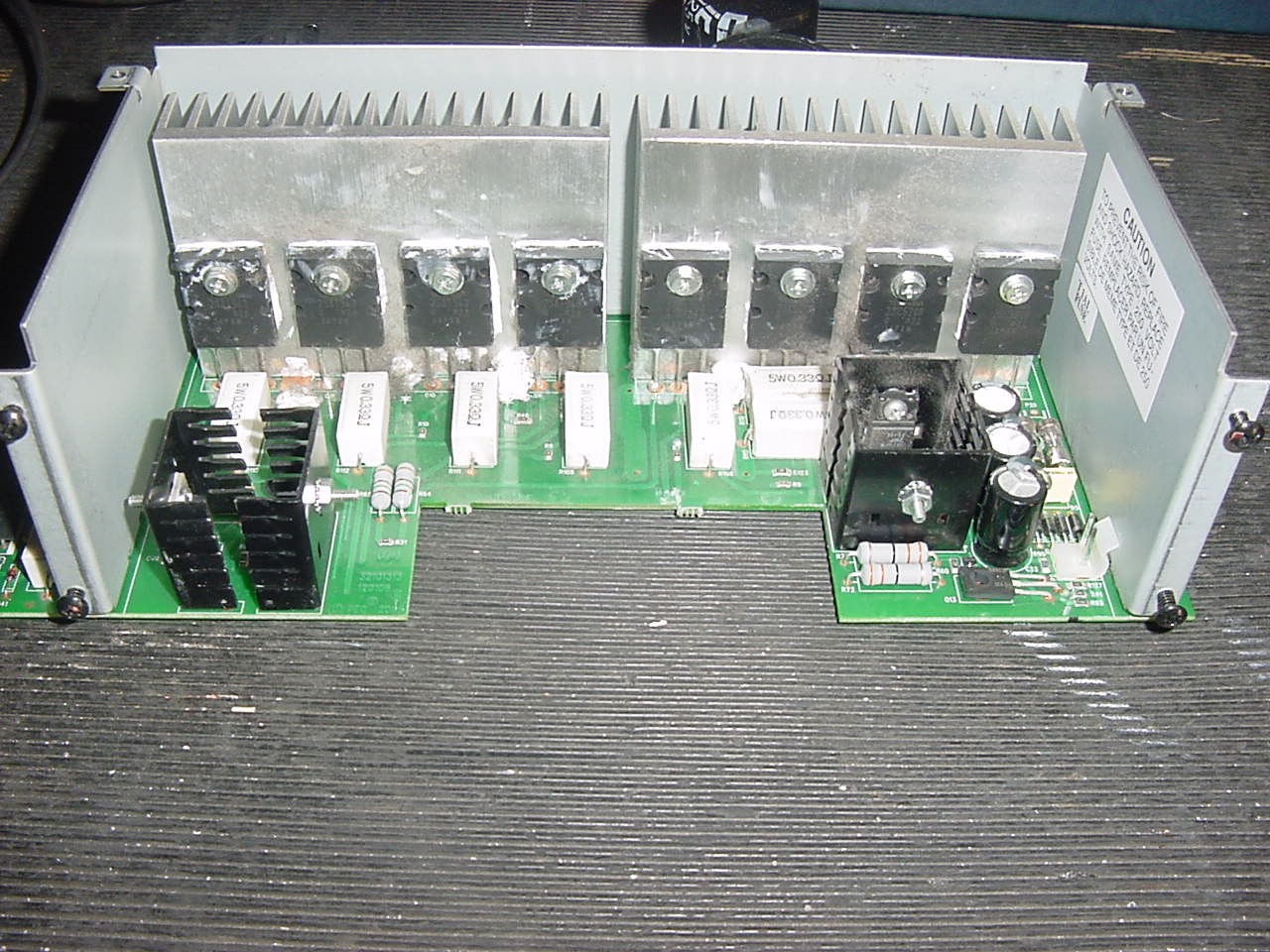
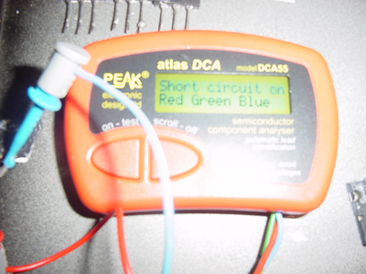
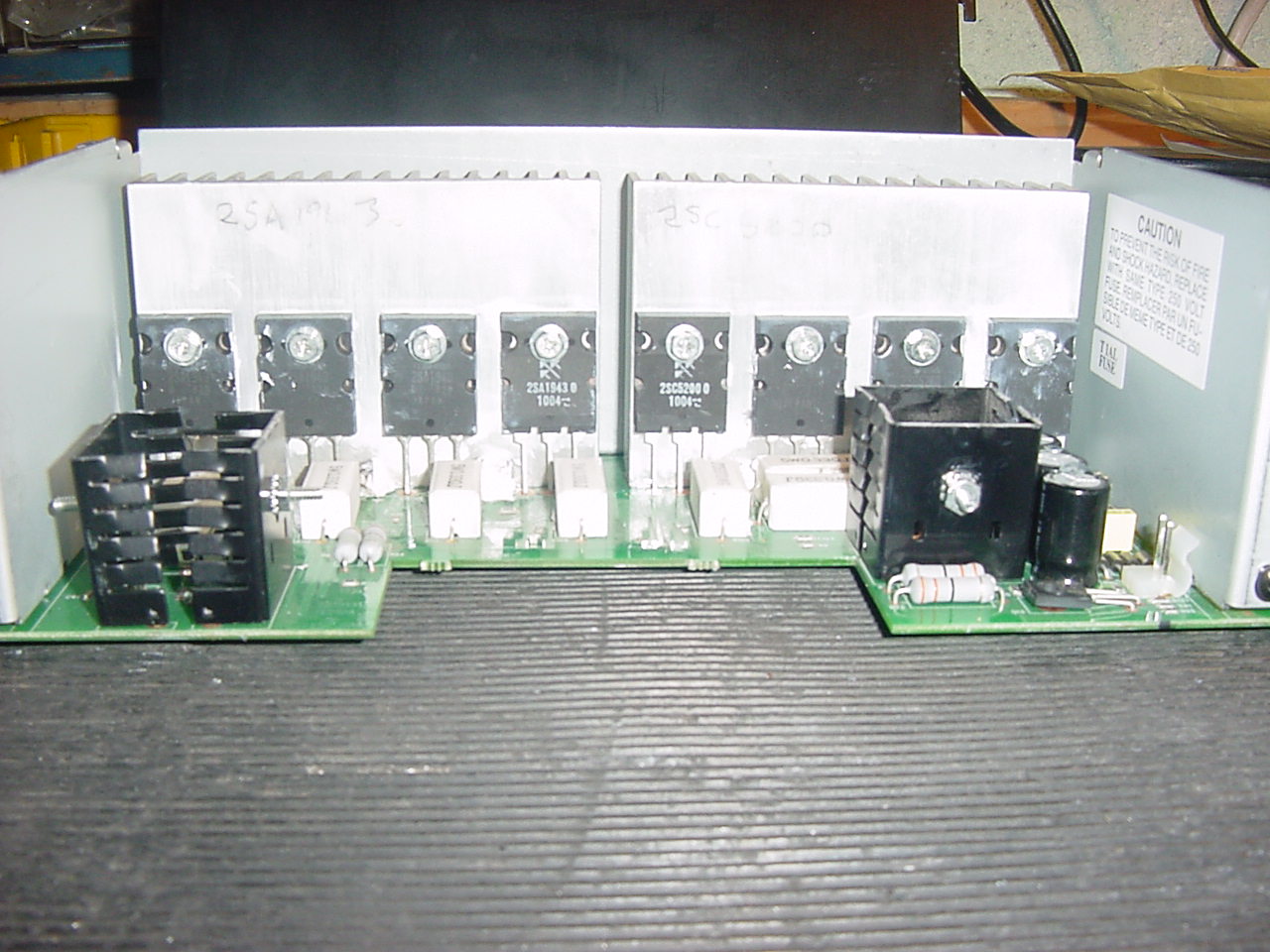
Found a short circuit on both sides of the output stage which was expected, removed all of the output devices 2SK1953 2SC5200 that seem to be the transistors of choice these days rated at 230v
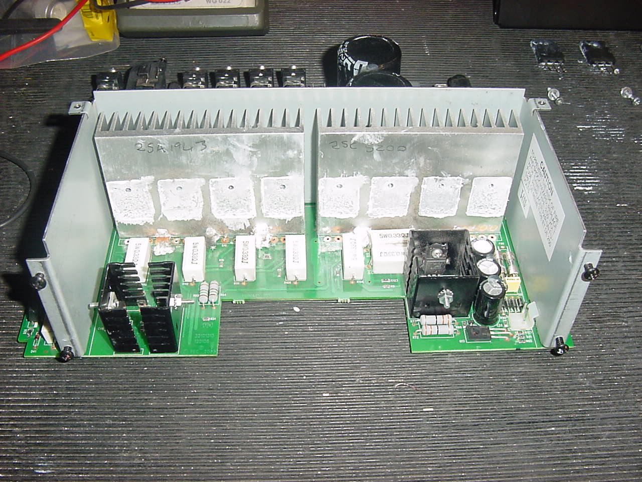
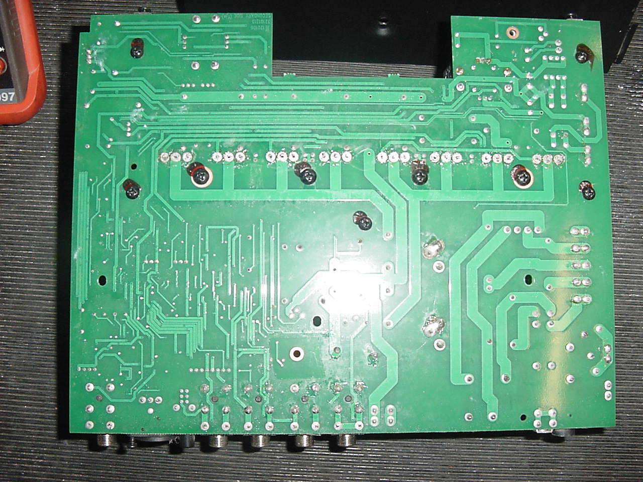
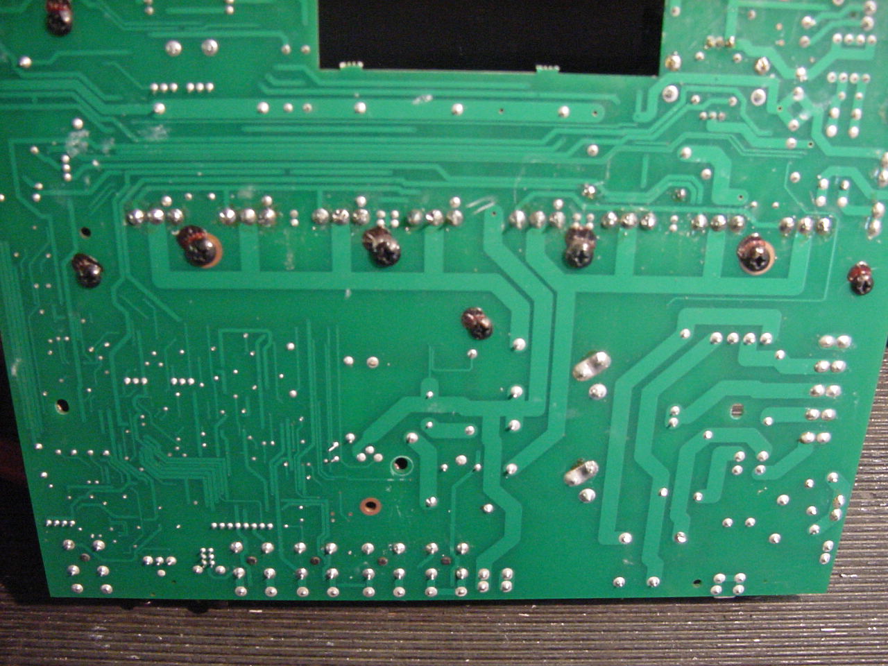
After removing all the devices they were tested - Even with our de -soldering station it was quite difficult to remove these transistors as can be seen we lifted a couple of pads on 2 of the devices centre pins however these were not connected on the top side of the PCB which is why they came away so easily, we found 2 devices short circuit - below centre
completely blown !
After going through our stock fitted 2 matched transistors and refitted all devices to heatsink
Before soldering
After soldering
Refitted chassis and main board
Re attached cables and tested
Found the Amplifier still did not work !
Took a few voltage measurements and found the output stage at 194v DC, the output protection relay was activated due to the protection circuit, found that the preamp power supply was missing the minus 16v rail. the readings were were plus16v and minus 0v also found the one of the PCB 1 amp fuses blown..
Removed the main board again and carried out a modification to the pre amp fuses, as we do not stock the PCB board solder type and they have to be ordered especially, we installed two 20 mm fuse carriers on the side bracket and hard wired them to the PCB, this enables fuses to be replaced without having to remove the entire PCB and chassis, also these fuses are readily available, this modification can easily be removed and put back to the original soldered PCB fuses if required just leaving 2 small holes in the chassis bracket.
Removed the main board again and proceeded to test the following
Output devices - all ok
Drivers - all ok
Pre Drivers - all ok
Protection clamp transistors - all ok
Tested the Neg Ve regulator - ok
New fuses ok
Something was pulling the minus 15v supply down but it was not the output stage? there was no short circuit measured on the minus 15v supply, after some more testing on and off over the next couple of days found the problem to be a short circuit 15v Zener that was fed through a diode, hence the meter on resistance range was unable to detect a short on the other side of the diode
Replaced the Zener and the op amp that was running on the 15v supply,
Re assembled the amplifier and tested - + and - 15v ok, protection circuit and relay working correctly, amplifier was now working, checked all the Gain, EQ controls etc, all looked good.
After repairing an amplifier with so much wrong with it we always leave the unit on heat soak for several hours - in this case 5 hours, testing about every hour steadily increasing the output each time from about 10w to full power, also testing the cooling fan sense was working - all ok
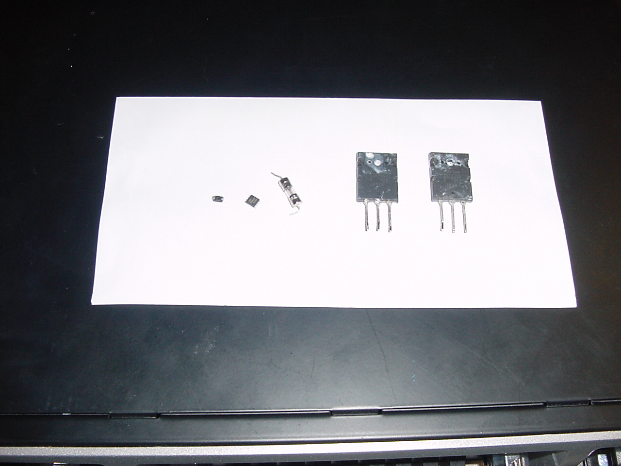
See bellow replaced components from left to right - 15v Zener, op amp, fuse, output transistors.
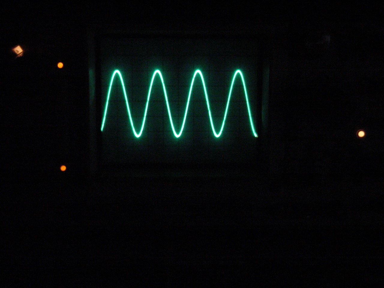
Tested unit - @ 700w RMS, 53v as can be seen on the Tektronics 475 scope
We hope the above information has been of assistance to those attempting a repair, we add more examples all the time, a lot of work goes into this section of our site from the doing the repairs, photos and answering technical support emails, to keep this a free service we rely on the goodwill of people who benefit and learn from the information supplied.
Please show your appreciation, feel free to make a donation no matter how small to keep this service going.
TELEPHONE (UK)
01803- 324589
TELEPHONE (INT) +44 1803- 324589

Head Office
UNIT ONE 61 WARBRO ROAD TORQUAY DEVON TQ1 3PP BACK TO REPAIRS PAGE
©2011 A&J AUDIO. All Rights Reserved.