
REPAIR SHOP
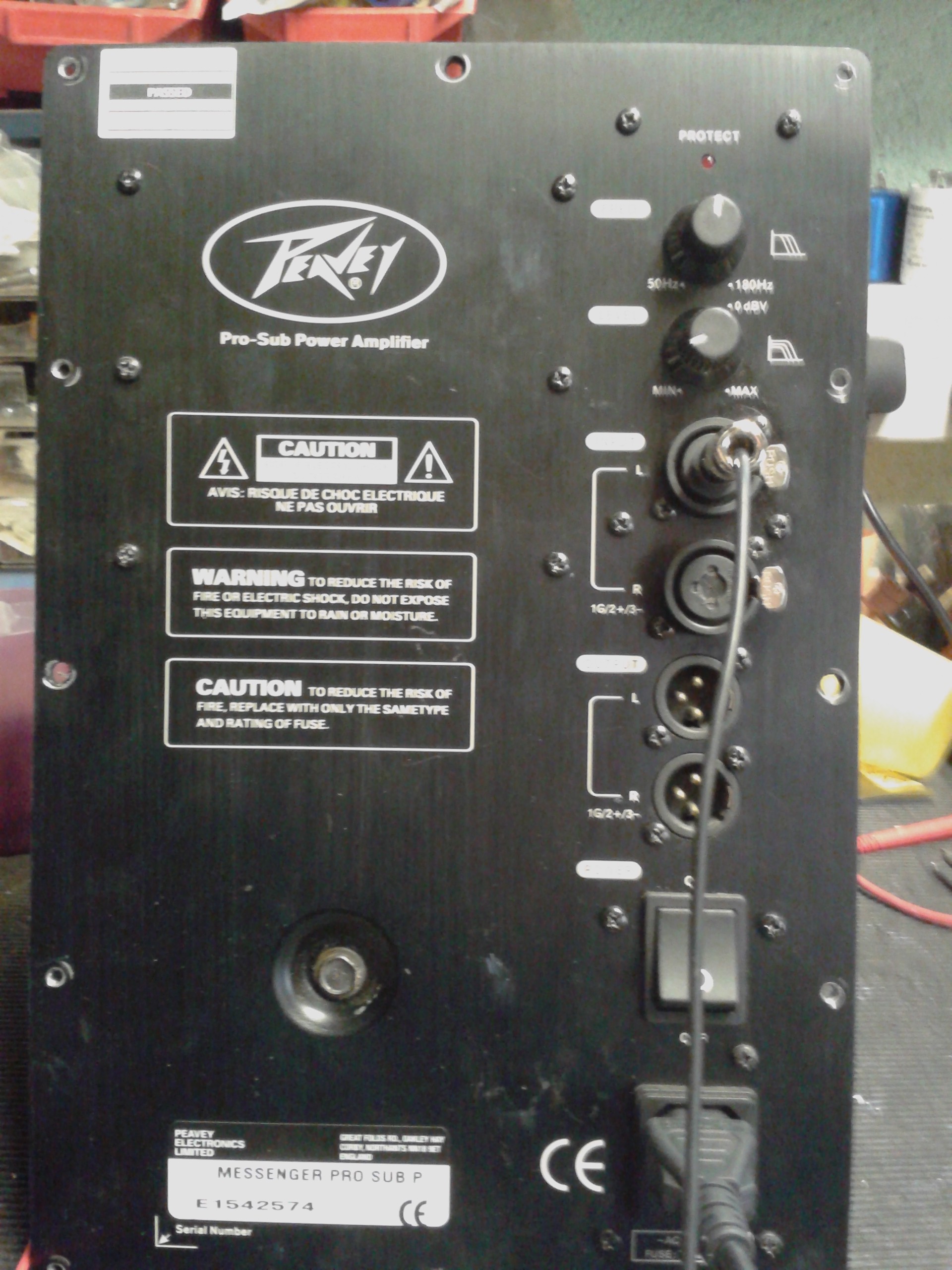
Repair of Peavy Messenger pro sub
Fault - Dead blows fuses
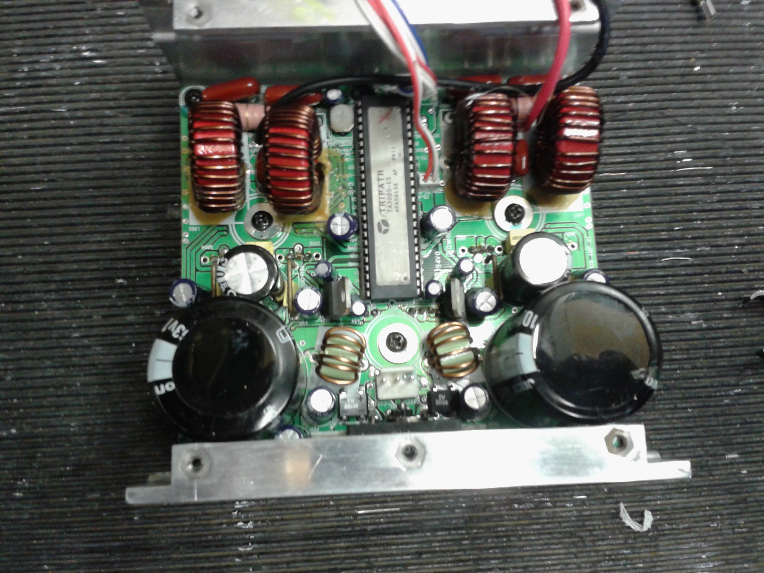
The messenger Pro Sub Amplifier section is a class D switching Amplifier that is also bridged, the heart of the amplifier is based around a dedicated TRIPATH chip TA3020, utilizing 2 pairs of switching MOSFETS and the usual LC filtering found on the output of class D amplifiers.
This repair is quite an undertaking and should not even be attempted by a novice and especially without a solder sucking station and a SMC re-work station, the following procedure should be valid for most repairs, as all the units we have ever looked at needed pretty much the same attention. We have not had the luxury of a service manual or schematic to repair these units, however the TRIPATH TA3020 application sheet provides almost all the information needed.
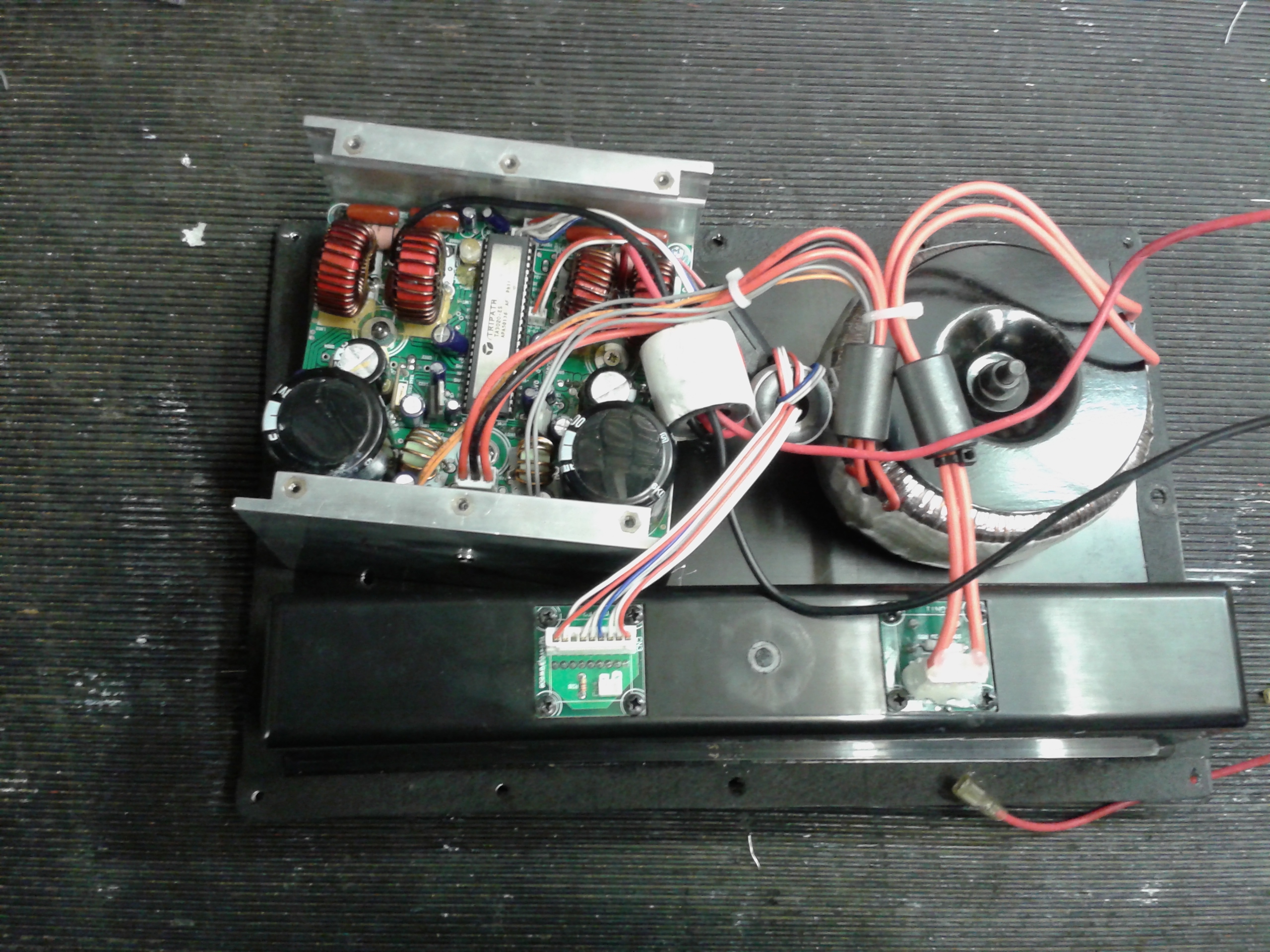
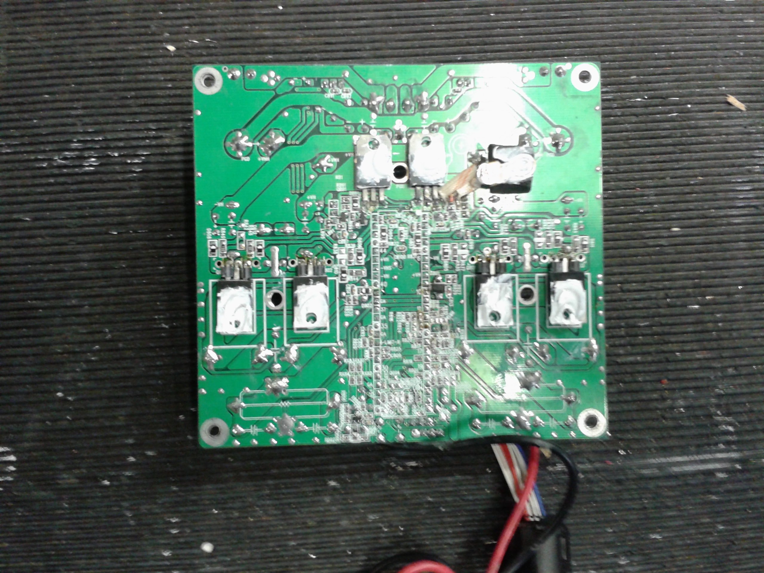
Remove the amplifier unit from cabinet, remembering to disconnect the speaker cables from the speaker and the LED cable plug, undo 6 screws to separate the heatsink/amplifier assembly from the back plate, disconnect 3 cables/plugs from the transformer and unplug cable loom plug from back plate chassis, undo the 3 screws in the middle area of the PCB and the nut/bolt fastening the bridge rectifier to the side of the heatsink, then undo the 4 screws in the corners of the PCB, then gently slide the PCB sideways out from the heatsink, put all the screws together with the heatsink and mica washers from the semiconductor devices that will be covered in white heatsink compound, gently clean the heatsink compound off all the semiconductors using a clean rag.
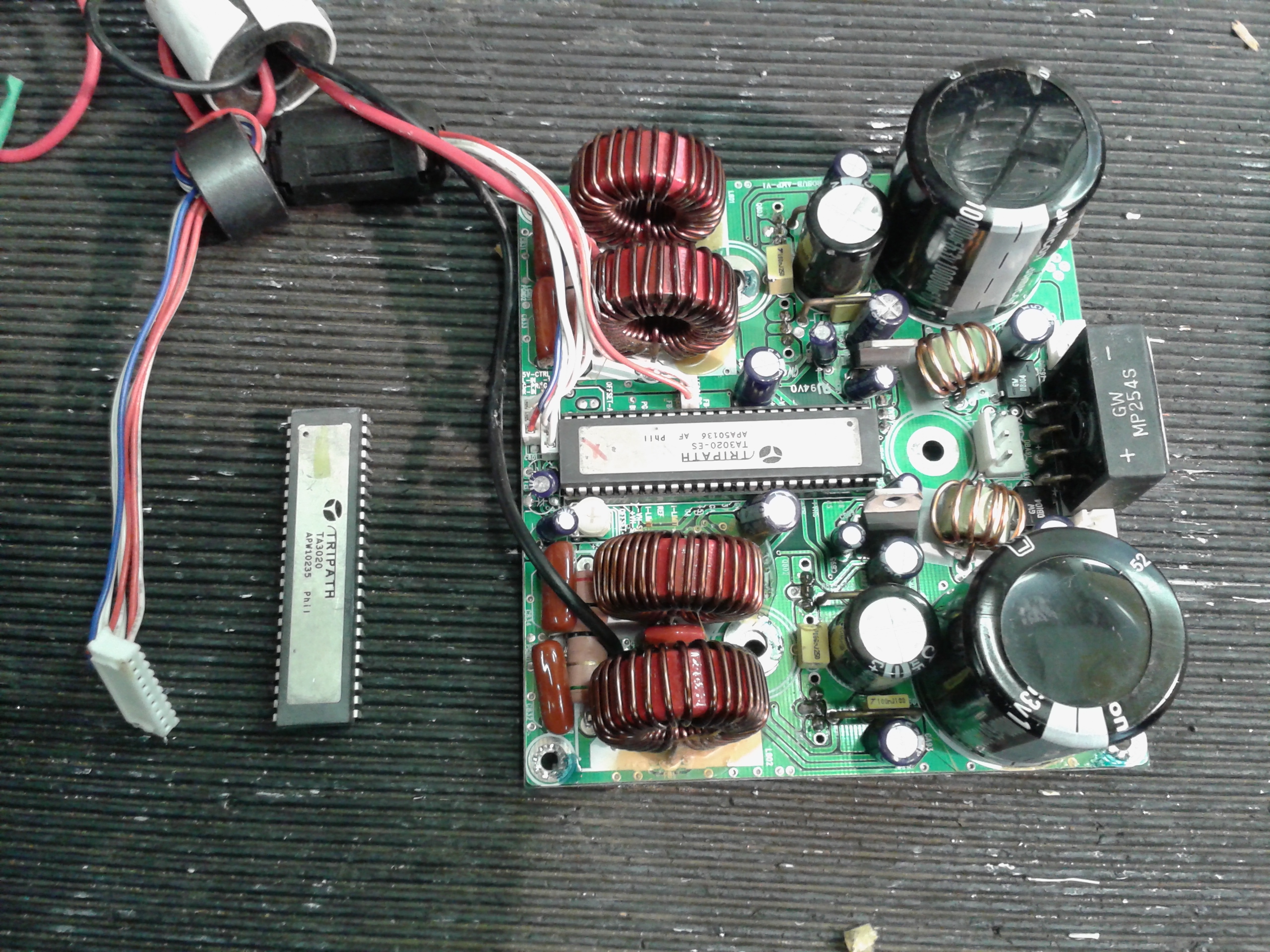
A visual inspection should be carried out on the PCB and components for obvious signs of damage, next using a multimeter on low resistance range check all 4 switching MOSFETS, in all probability you will find 1 or more short circuit, if short circuits are found at this point very carefully remove the TA3020 easing it out without damaging the pins (there are 48) then re test the MOSFETS you might find you get different readings this occurs when the chip has gone short circuit, in any case it is a good idea to replace the chip with a new one - but not yet leave it until later on.
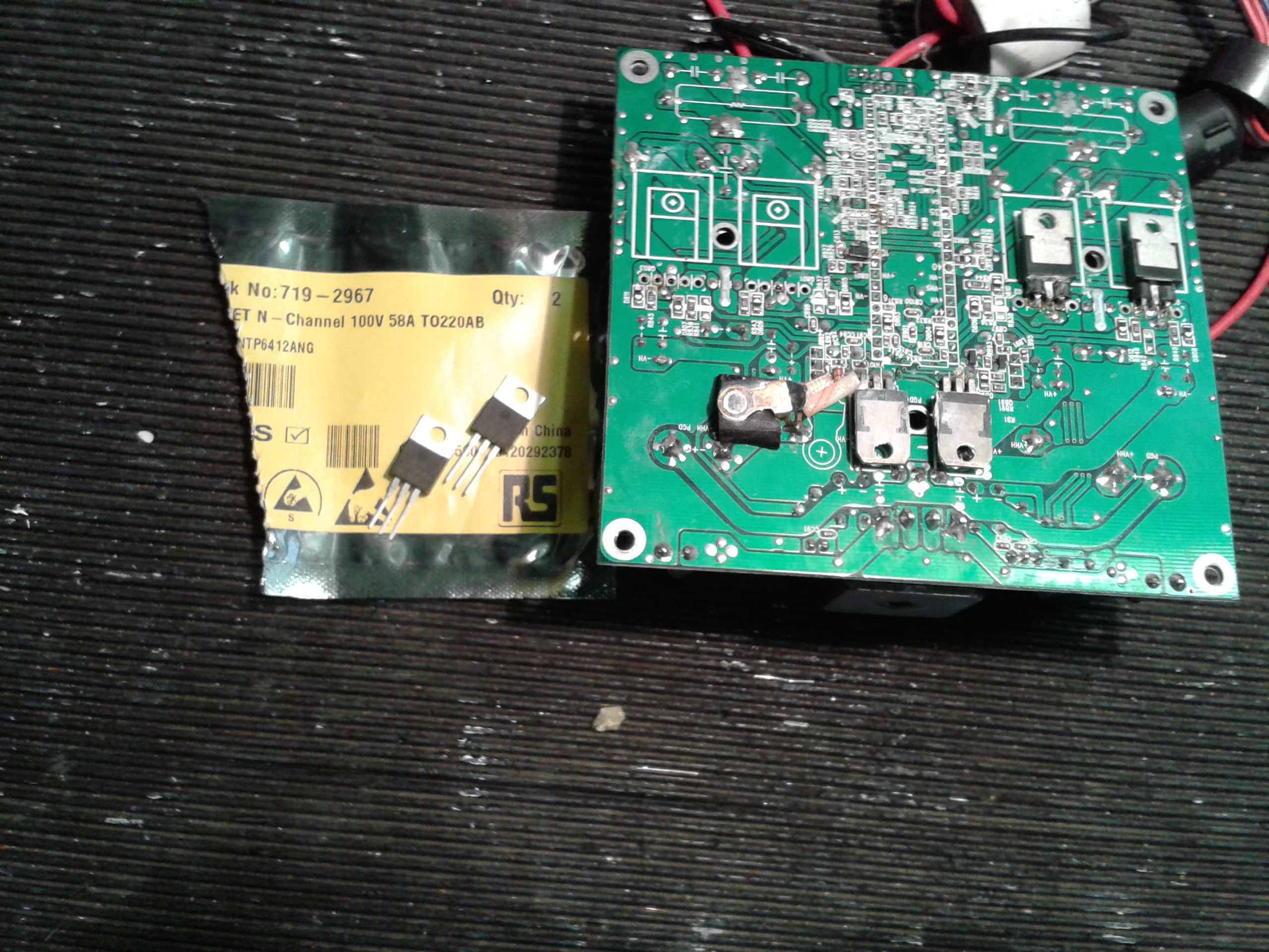
Carefully unsolder and remove the suspected faulty MOSFET devices - usually just 1 pair will have blown, we have a semiconductor tester that will confirm the correct operation of the devices, if you do not have a semiconductor test meter this just replace all 4 devices, the correct devices are 75639P 56 amp 100v MOSFETS, use correct replacements, if you are unable to source these, other devices can be used, we have used NTP6412ANG 58 amp 100v MOSFETS which seem to work very well with this amplifier (these were used due to the unavailability of the correct devices at the time)
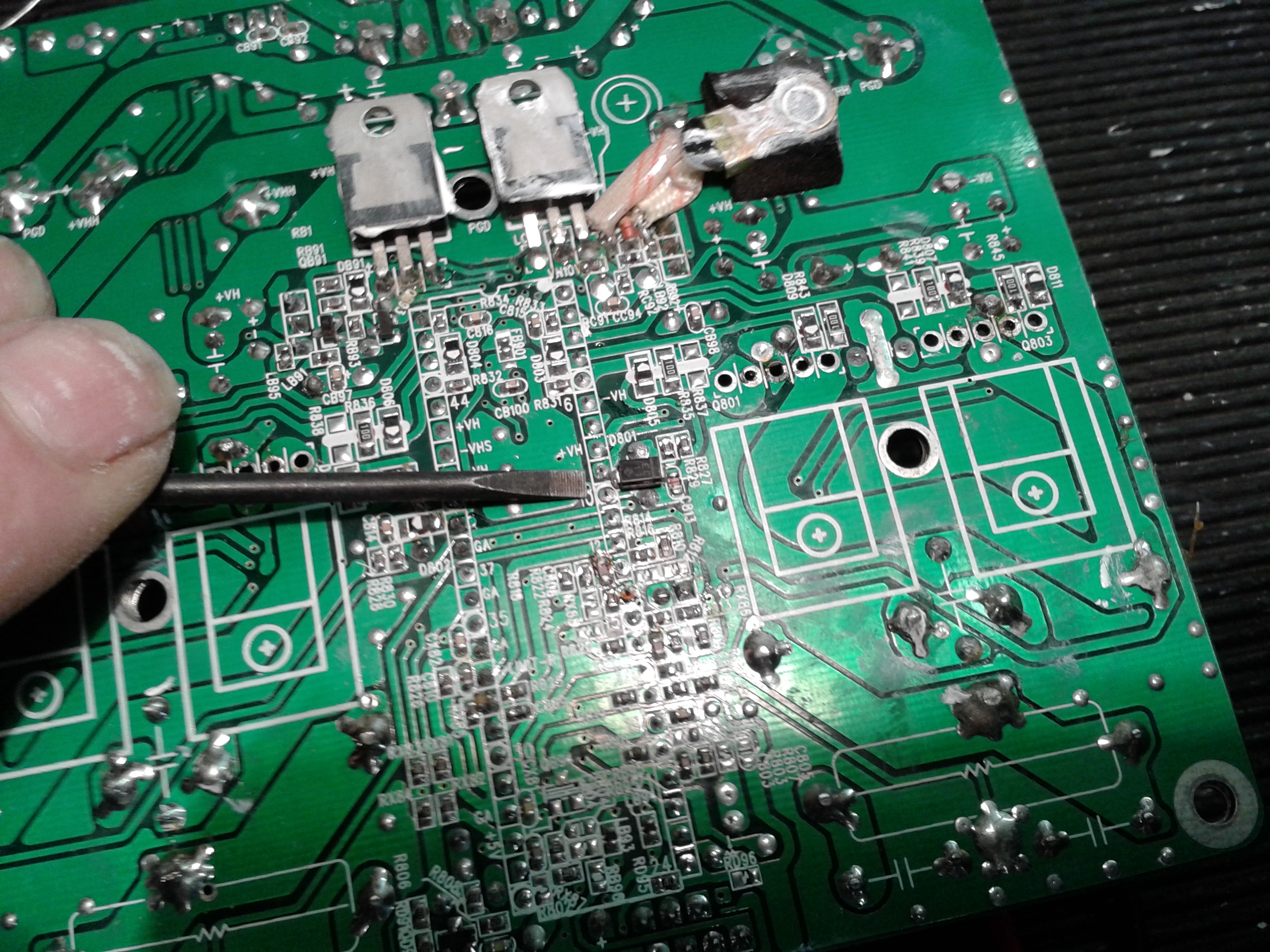
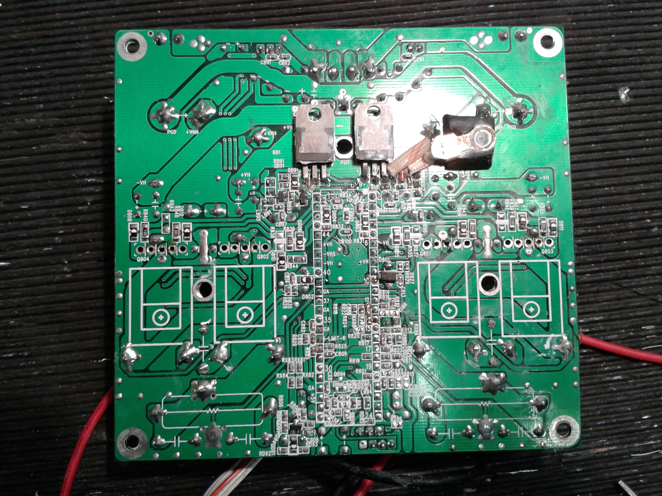
Before soldering the new devices in position you need to check particularly 2 SMD diodes that feed the gate drive 10v supply to pin 10 and pin 40 on the TA3020 (see picture) they are absolutely tiny but can be measured on diode range of a multimeter - they should read about .4v to .5 v or so and nothing in the other direction, if one of these is damaged and it almost certainly will be on the diode feeding the blown MOSFETS, it needs to be replaced, carefully remove this diode with the SMD re-work station, the application sheet recommends using MUR120 diodes which are available in SMD versions, however we have used successfully 150v ultra fast diodes that work well and just about fit in the space available although a bit on the large side,
From the above picture you can see the replacement diode in position, some of you will notice it is not exactly straight, however it is not touching any of the adjacent components and is well soldered so we decided rather than risking unsoldering and disturbing anything else it is best to leave as is, if you want perfection you are on the wrong web site.
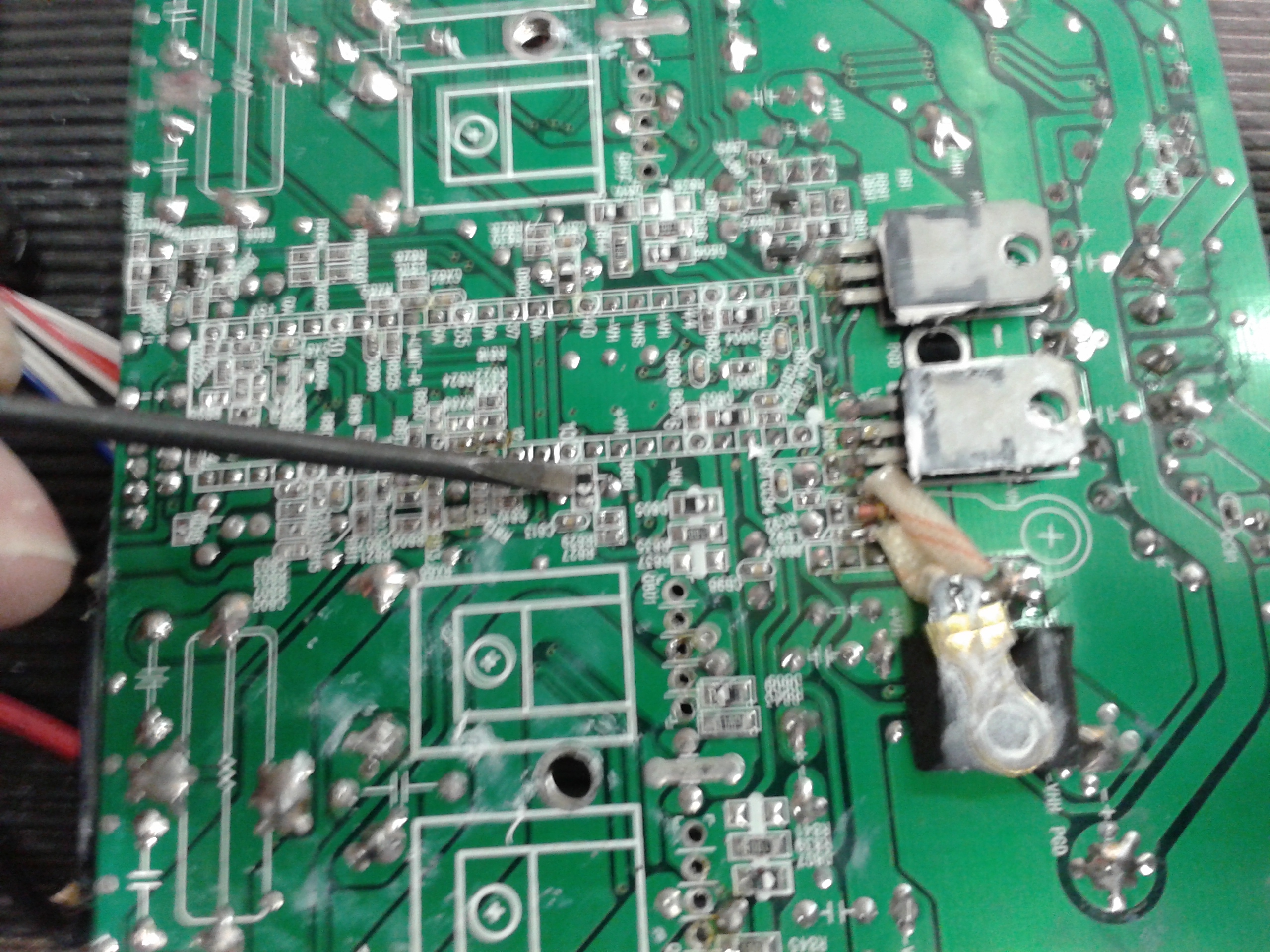
If you have had to replace one of these diodes almost certainly you will probably need to replace the LM317T regulator that feeds the diodes with the 10v supply as usually these blow as well, very carefully unsolder, remove and replace the LM317T regulator located on the underside of the board (one of the 2 TO220 devices located next to the heat sensor either side of the middle hole) .
After the diodes and regulator have been replaced you should be able to read .4v to.5v from the middle (out) pin of he LM317T regulator to pin 10 and pin 40, the pin numbers are marked on the PCB.
You must also check all the other diodes on the board, most are in parallel with 10 ohm resistors so you should not read any lower than about 9.5 ohms, the diode testing function will not work whilst testing these diodes, there are some catching diodes D803 and D804 that are not in parallel with resistors and we find these also sometimes blow as well, use a magnifying glass and meter look for a pin prick size explosion/Pock mark in the centre of the diodes usually discolouring the white mark on the diode, they measure short or open circuit, if in doubt remove and replace the diodes with an MUR120 or equivalent.
We did have a blown 10ohm resistor and diode on one of our repairs, unless you have access to lots of surface mount resistors this could present a problem, there are two options.
Option 1- use the smallest resistor you can find and carefully solder into position, there are some really small resistors available.
Option 2 - scavenge a surface mount resistor of the correct value from another board - we tend to keep blown boards from Flat screen TVs and PSUs etc in a scrap bin for this very purpose.
Having completed all of the above
Carefully fit and re-solder the MOSFETS with the 2 ferrite rings on the outer legs
Resistance test between the legs of the MOSFETS looking for short circuits caused by bad soldering
With a magnifying glass and meter - check the replaced diodes are not shorting out with any adjacent components and are well soldered in position.
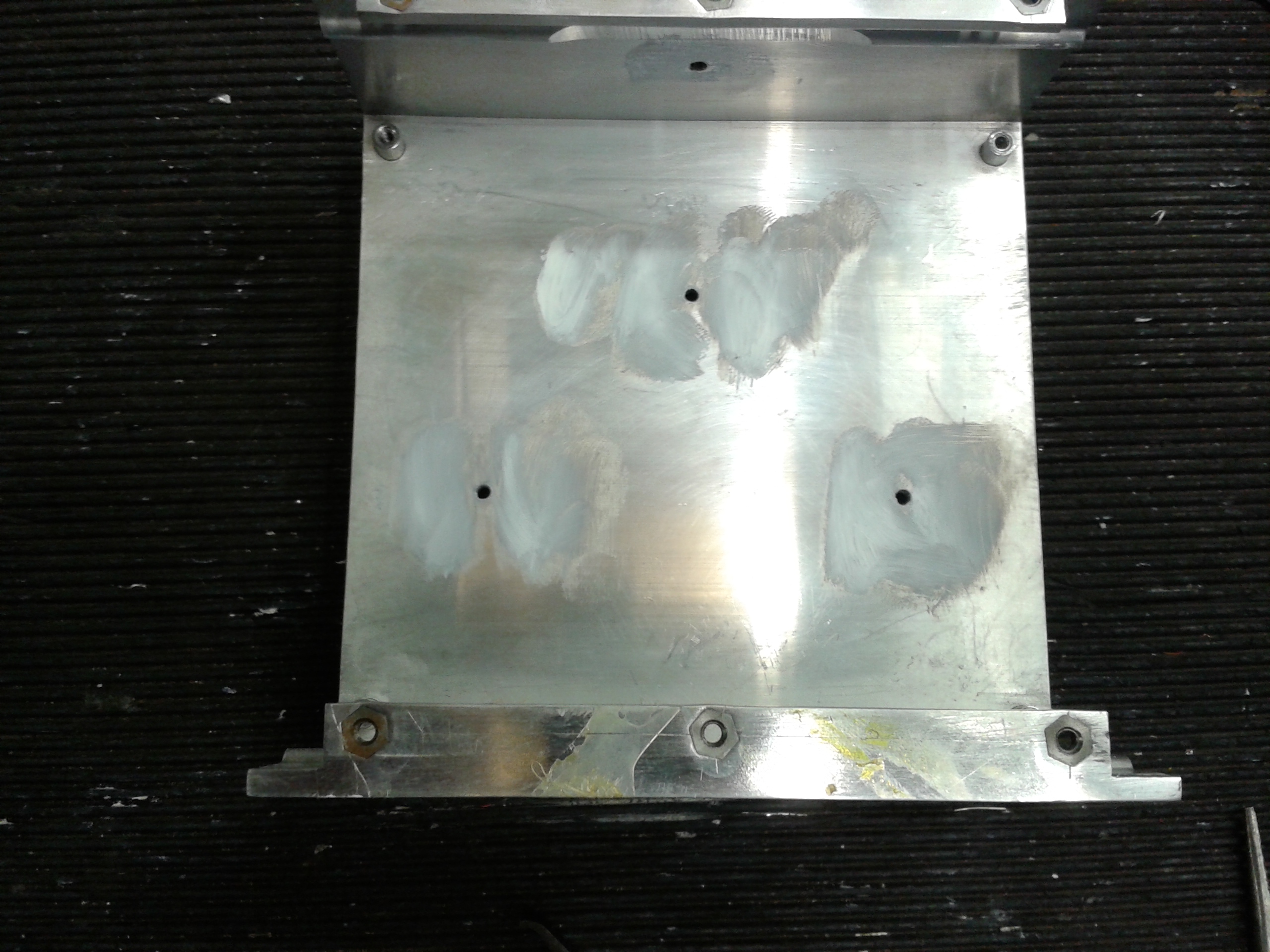
You now need to clean the old heatsink compound off the heatsink, then apply a thin fresh layer either side of the 3 fixing holes, then get 7 new TO220 mica washers, spread new heatsink compound onto all 6 of the TO220 devices and the heat sensor, then carefully put the mica washers on to the devices working the compound in evenly, position the mica washers correctly - they should be stuck in position by the compound, then gently slide the PCB into position and carefully screw the 4 corner PCB screws in - followed by the 3 screws in the middle area of the PCB, lastly fit the fixing screw for the bridge rectifier on the side of the heatsink.
Having completed all of the above
RESISTANCE TEST THE MIDDLE LEG OF ALL THE T0220 DEVICES EXCEPT FOR THE 5V REGULATOR, FOR SHORT CIRCUITS TO THE HEATSINK the middle legs are connected to mounting tab of the devices so short circuit to the heatsink* indicates the mica washers are not correctly positioned, in this case remove the PCB from the heat sink and start again, *with the exception of the 5v regulator where the middle pin is grounded, (this is not the LM317T that you may have replaced)
DO NOT FIT THE NEW TA3020 YET
You are now ready to do some bench test measurements
Lay the heatsink and back plate on the bench, get a piece of thin tinned copper wire about 12" long and connect one end to the heatsink using one of the 6 fixing screws and the other end to the back plate using a screw and nut thus grounding the heatsink to the face plate, next reconnect the 3 transformer connecters to the PCB and plug the loom into the back plate connector.
Find the small rectifier feeding the LM317T, it is adjacent to the small plug from the transformer with the just 2 grey cables, find the neg output pin of this rectifier
Plug the the mains lead into the faceplate and turn mains on, with the multi meter on DC Volts put the black probe onto the neg of the small rectifier and the red probe 1st on pin 10 of the IC holder and then pin 40 you should read about 10 v on each pin, if this is so you have proved out the LM317T and diodes for the 10v gate drive supply
Next with the black meter probe connected to ground
Check for + 50v on pins 43 - 7 and - 50v on pins 41 - 39 - 8
Check for 5v from output of the regulator next to the LM317T
Check for + 12v and - 12v at the outputs of the 2 regulators on the PCB
If you do not get these readings test again carefully - if not remove the PCB from the heatsink and check everything again.
After everything has tested ok, turn off mains and allow half an hour for all capacitors to fully discharge
Very carefully using a grounded anti static wrist strap fit the new TA3020 THE CORRECT WAY ROUND, check all the pins locate into the IC holder
Connect a speaker or 8 ohm dummy load to the speaker cables, also connect a multi meter to across the load on DC Volts
Turn on the mains and hold your breath - you should find a few hundred mV across the load this needs to be be nulled using the preset pot on the PCB, adjust this level as low as possible + or - 10mV should be fine, monitor for any changes to this, you may find it drifts a bit but as long as this is not to severe do not worry.
Apply an input signal all should now be working ok - just leave for an hour on very low volume, the heatsink should become warm but not hot, the output inductors do get a bit hot - this is normal.
If all ok switch off, re - assemble heatsink to the back plate and refit into cabinet connecting the speaker and LED connector.
The unit is now ready for a tougher test at higher volume levels.
The nature of this repair means after setting the offset and getting the amplifier working there is not a great deal else to do other than testing for a period time, the amplifier will either work and be reliable or it won't
If available you might consider a complete replacement amplifier PCB
I do not like these chip controlled class D amplifiers, in fact I believe although still available the TA3020 is just about obsolete.
We hope the above information has been of assistance to those attempting a repair, we add more examples all the time, a lot of work goes into this section of our site from the doing the repairs, photos and answering technical support emails, to keep this a free service we rely on the goodwill of people who benefit and learn from the information supplied.
Please show your appreciation, feel free to make a donation no matter how small to keep this service going.
TELEPHONE (UK)
01803- 324589
TELEPHONE (INT) +44 1803- 324589

Head Office
UNIT ONE 61 WARBRO ROAD TORQUAY DEVON TQ1 3PP BACK TO REPAIRS PAGE
©2011 A&J AUDIO. All Rights Reserved.